Now we are going to see how to generate a complete graphical editor for the EMF model we created in preceding tutorials, Library.ecore.
For this purpose, we need to work with another framework, Graphical Modeling Framework (GMF), currently included in a broader set of Eclipse Projects, Graphical Modeling Project (GMP).
A s the official Wiki states, GMF ÔÇ£provides a generative component and runtime infrastructure for developing graphical editors based on EMF and GEFÔÇØ, that is it acts like a bridge between EMF (that allows the model definition) and GEF (a lightweight graphical framework, based on MVC architecture), generating the complete infrastructure needed to coordinate the modelÔÇÖs objects lifecycle (EMF EObject) and their corresponding graphical representation (GEF EditPart).
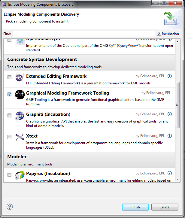
To use GMF in our projects, we need to install the GMF Tooling component; the fastest and easiest way to do this is to select (from main menu of our Eclipse installation) Help >> Install Modeling Components:
In next screen, we choose ÔÇ£GMF Modeling Framework ToolingÔÇØ:
We continue by clicking on ÔÇ£FinishÔÇØ, accept the default settings and then we click ÔÇ£Restart NowÔÇØ to complete the installation.
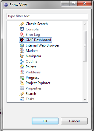
Now we are ready to start developing our editor; for this purpose we will use a tool included in GMF Tooling: the GMF Dashboard. To display it, we select Window >> Show view >> Other >> GMF Dashboard:
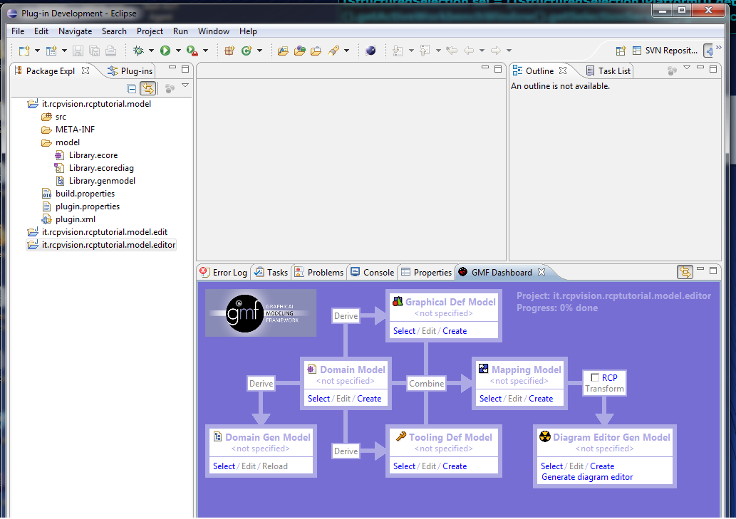
After this operation, our IDE is looking like this:
Let’s take a minute to examine this new tool: Dashboard exists to guide the developer in the process of generating the correct configuration file of a project GMF, allowing you to generate all the files and the code needed following an iterative process (very similar to that already seen for EMF model generation) starting from the template file (*. ecore) and ends with the creation of the build file of the diagram (*. gmfgen); this process can be performed as many times as you want to gradually refine the final result.
At this point we have two choices: we can create a new project (GMF Project type, category that now we will find in the list of wizards) or continue to develop the original EMF project; we will follow this second path, as the simplest and most suitable way for this tutorial.
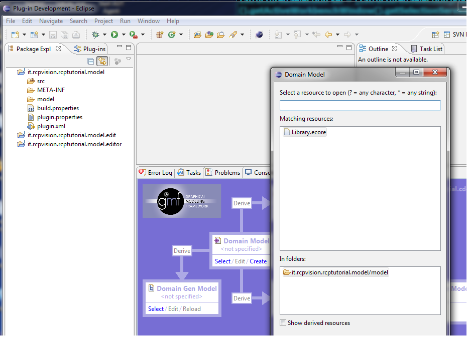
Then select the project it.rcpvision.rcptutorial.model in the Package Explorer window; in the Dashboard, Domain Model pane, click on Select: this opens a dialog box that allows us to select the template file; for in our workspace there is only one file with these characteristics, we find preset:
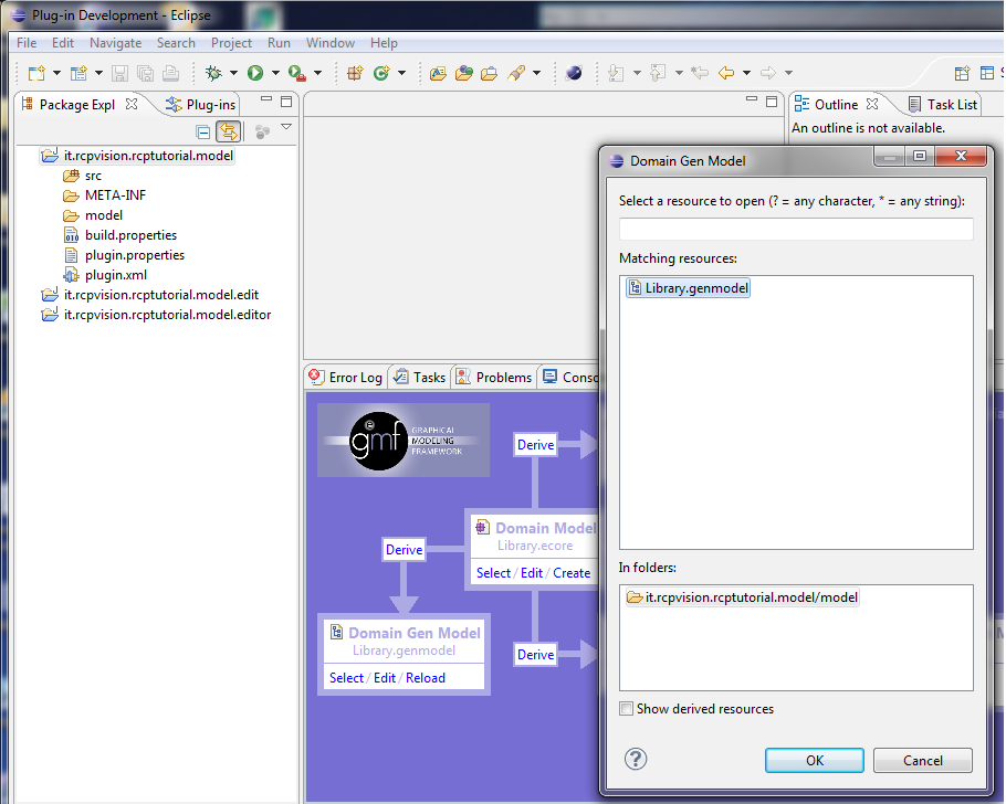
We accept the proposals and continue clicking OK; the next step is to create (clicking on the button Derive) or selection (if already exist) to the *. genmodel file: since we have already created in the early stages of the tutorial on EMF, in this phase we click on the Domain Gen Model pane, Select option, and accept the default already identified by the tool:
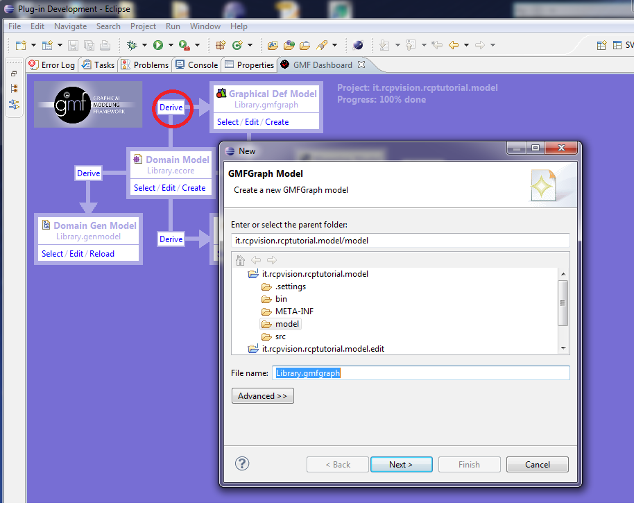
At this point, clicking on the button Derive above the Domain Model pane, we proceed with the creation of the *. gmfgraph:
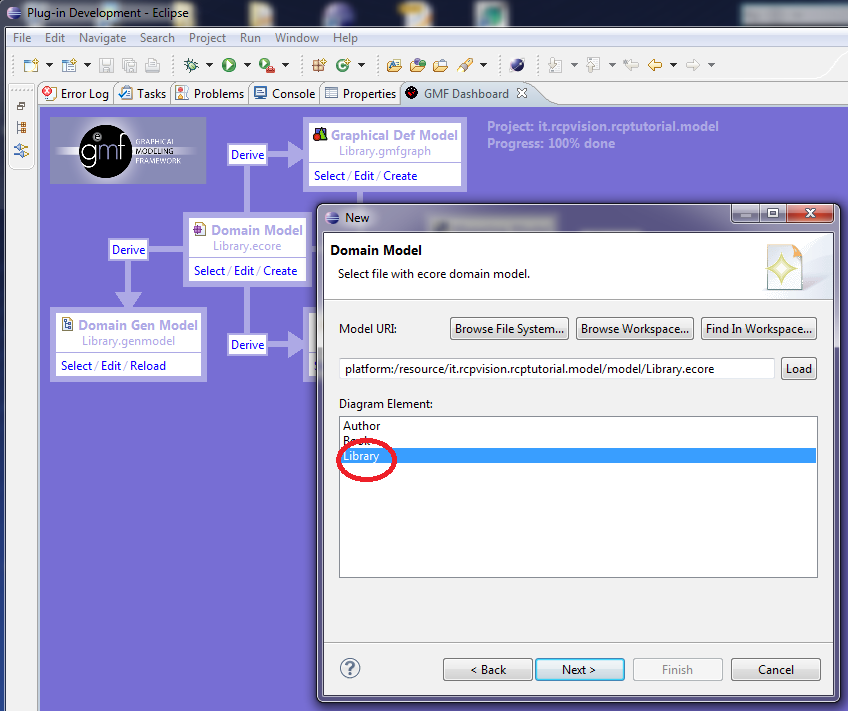
We accept the default values ÔÇïÔÇïfor the file name and destination folder, and continue clicking on the Next button; we will get a dialog box that asks the URI of the template file and which element we want to set as the Diagram Element:
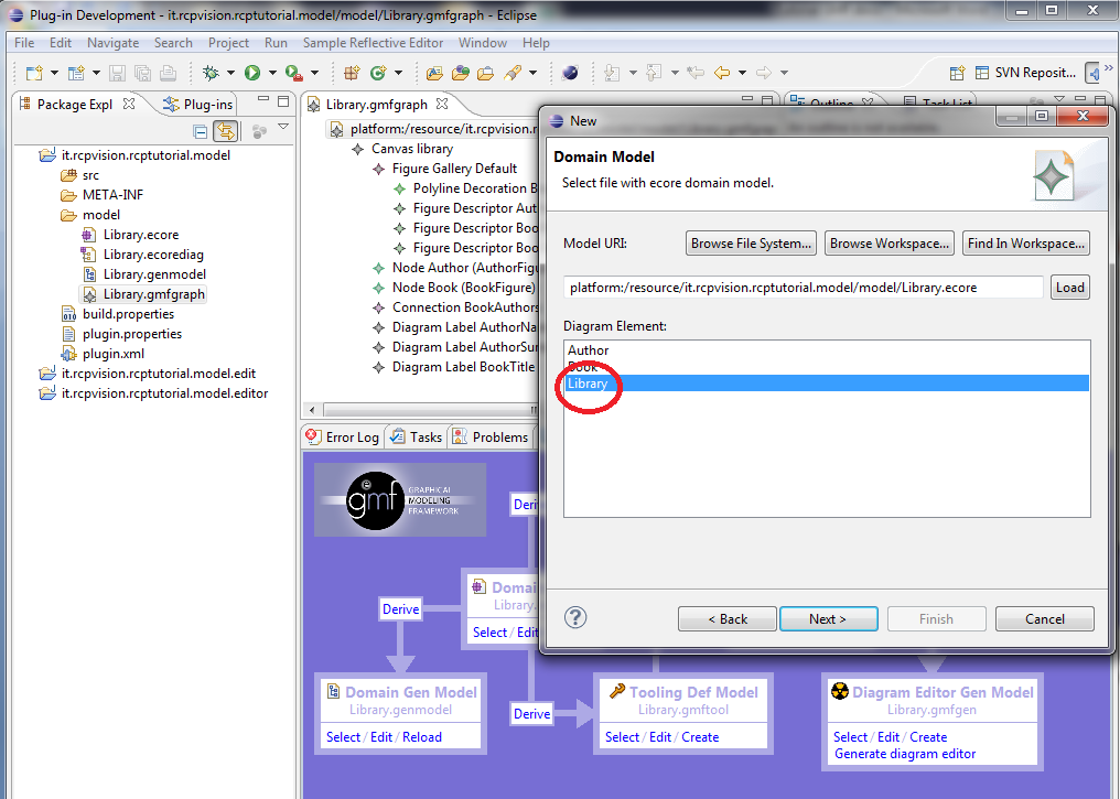
To understand this request we must come a time in the generation logic of the editor that we are going to create : the tooling creates an editor with (potentially) many diagrams, in which you can create, edit and delete graphic objects that are instances of model objects … but the diagram itself corresponds to which object? As a rule (but not always, and not necessarily) is sufficient to match the chart with “root” object of our model; fortunately, since the model that we are running is very simple, so simple is the answer to the question, then select, as Diagram Element, the Library object. As the editor weÔÇÖll get to the end of the process can handle n diagrams, this implies that for each diagram we will open again, we will be implicitly creating a new instance of the Library object. We continue by clicking on the Next button will open a new window:
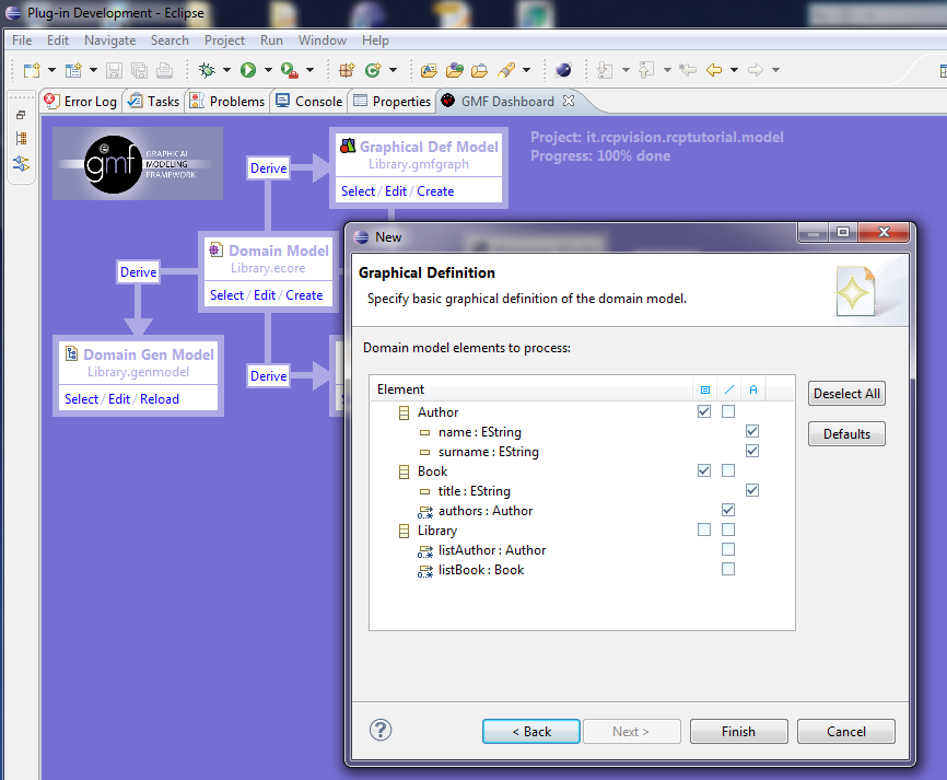
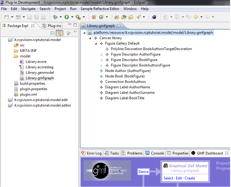
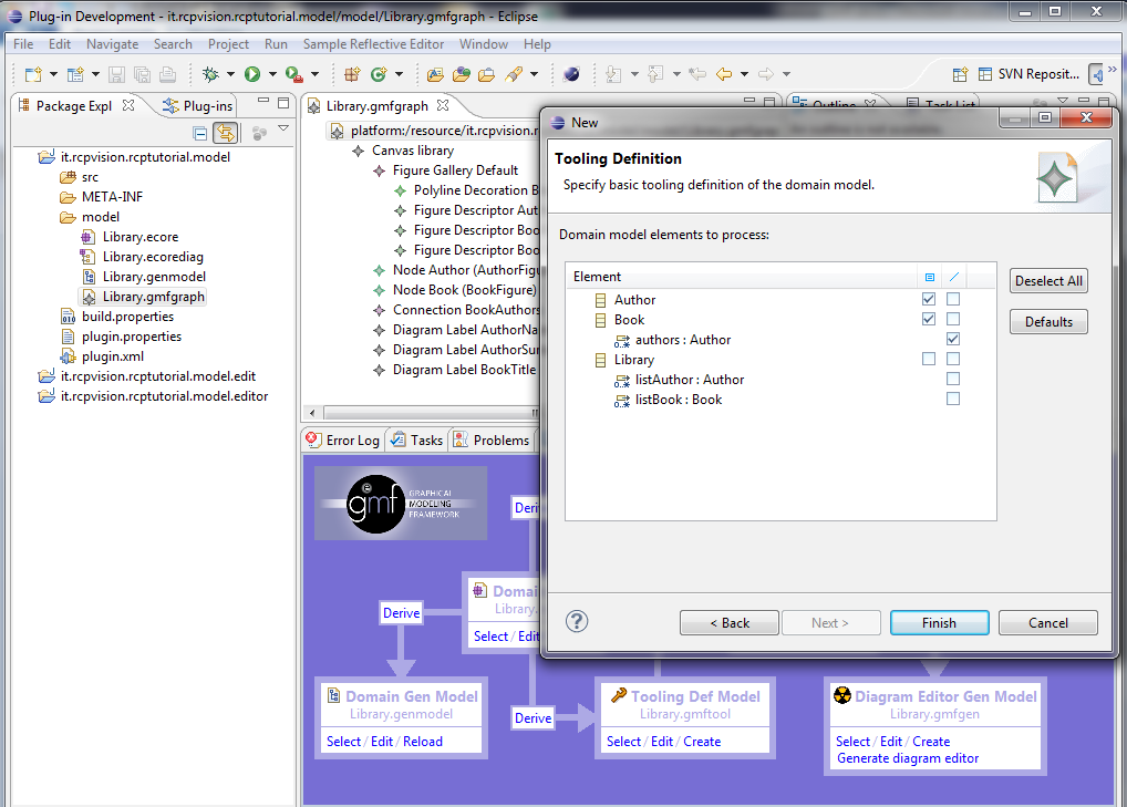
In this window we are asked to declare which objects and properties of the model we want to be in the form of Nodes (plane figures), Connections (lines) and Labels (text labels); then as selected in the window, we plot the Author and Book objects represented as figures, author’s name and title of the book represented by labels and finally the relationship between book and author represented as a connection. We accept the proposals and continue clicking on Finish: this causes Library.gmfgraph file creation and its opening with a dedicated editor
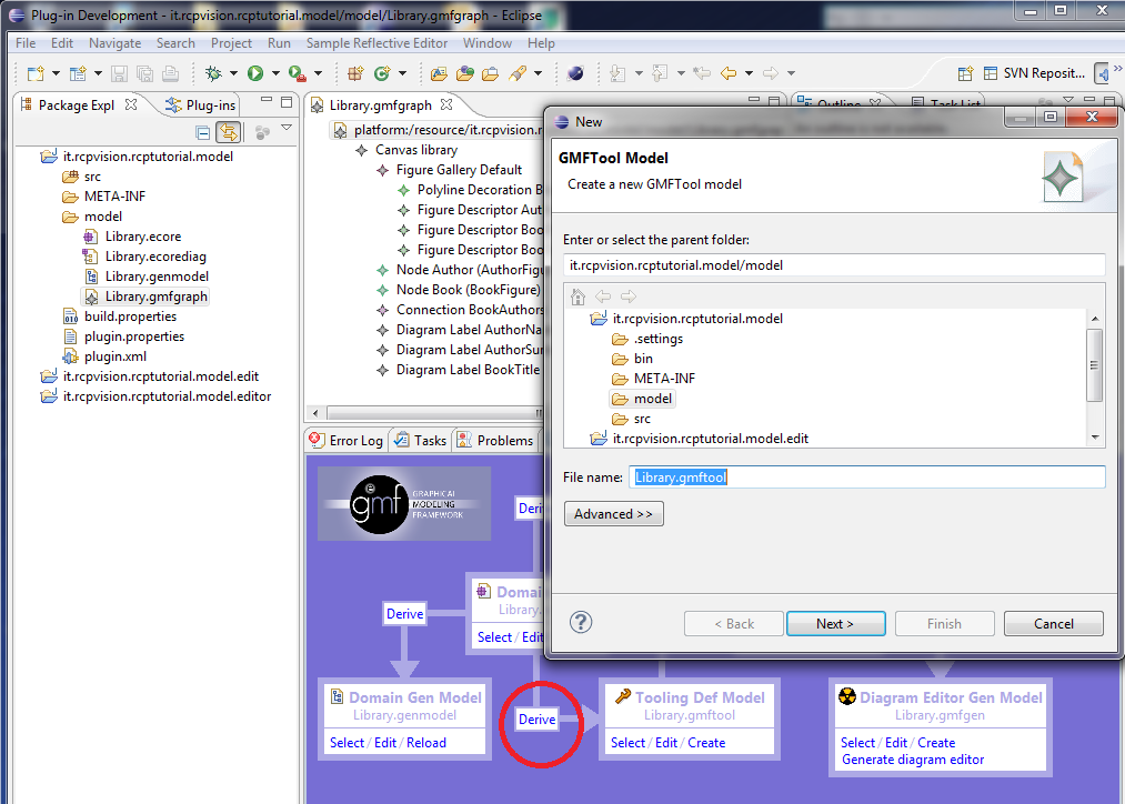
We continue by clicking on the button Derive beneath the box Domain Model: this causes the opening of a window where we can choose the destination folder and the name of file *. gmftool:
The GMFTool Model is the file that defines what and how many tools we want to create to appear in the Palette that will be generated in our editor; accepting the defaults and clicking Next will open another window of choice:
We are again asked the URI of the model and the Diagram Element: confirm the library object and click Next, open the following window:
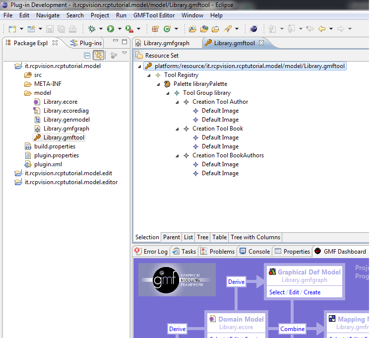
The tools that appear in the Palette are of two types: CreationTool (corresponding to Nodes) and ConnectionTool (corresponding to Connections): as the default, which gives us the tool is perfectly suited to our needs, we confirm with Finish, this involves the creation and the opening (with dedicated editor) Library.gmftool file:
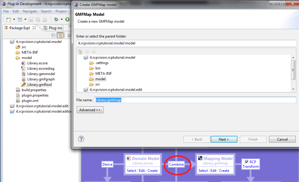
Now click on the Combine button to the right of the box Domain Model: it will get the opening of the window generating the *. gmfmap:
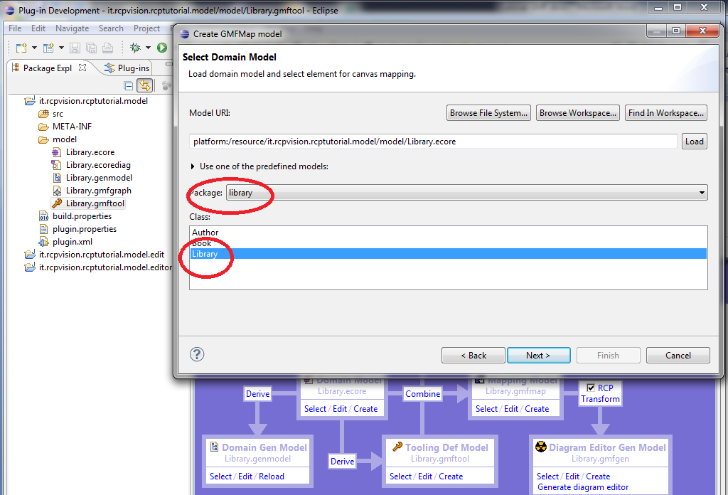
We accept the defaults and continue clicking Next: there is the proposed new window to confirm the model, the Diagram Element and the package
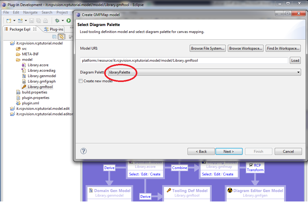
click on Next, the window appears in which we confirm that we intend to use libraryPalette:
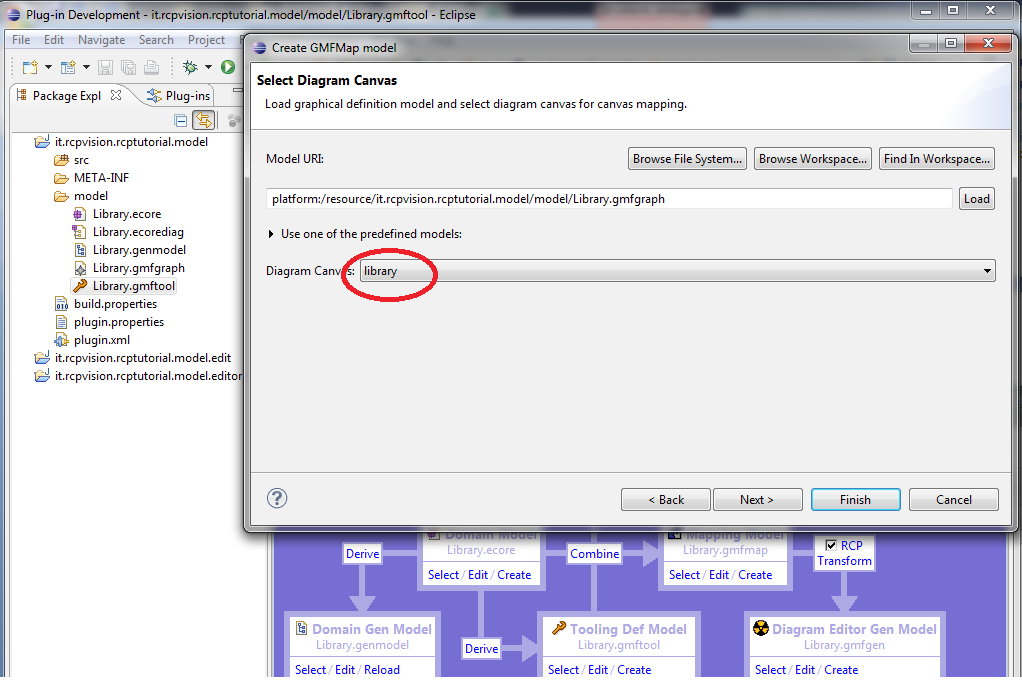
clicking on Next, the next screen asks us confirmation of graphics:
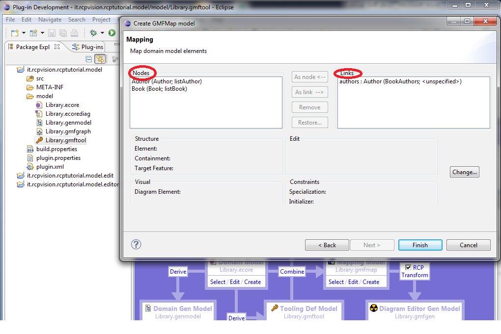
Finally, the last screen gives us the final mapping between objects and images
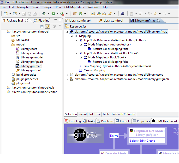
because the default is what we want, we finish the process by clicking Finish: this causes the creation and opening of file Library.gmfmap:
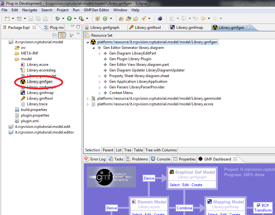
At this point, select the RCP checkbox by the Dashboard (because we want to create a standalone application, rather than a simple plugin) and then click on the Transform link below
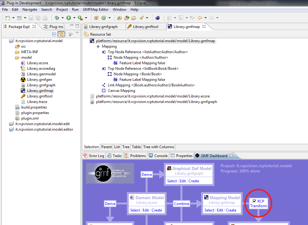
This causes file creation Library.gmfgen
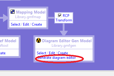
and finally from the Dashboard, box Diagram Editor Gen Model , we click the item Generate diagram editor
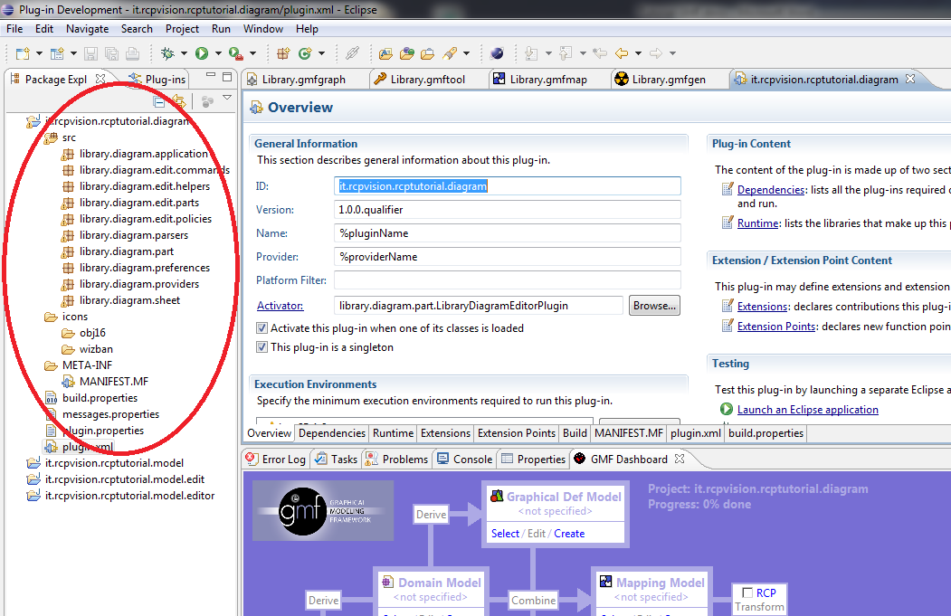
This operation starts the process of generating a new project, it.rcpvision.rcptutorial.diagram; the end, our IDE looks like this:
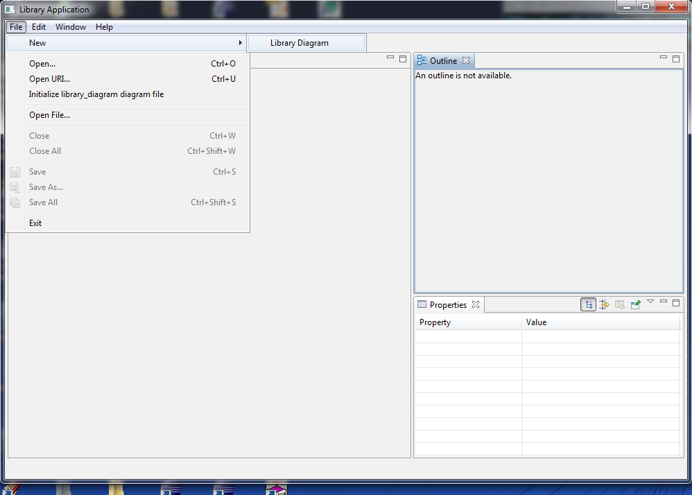
Finally we are ready to see the result of our effort: we open the plugin.xml file from the new project, the Overview tab, Testing section, select the Launch an Eclipse application link e. .. voila, here is the result of our efforts!
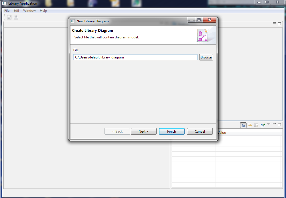
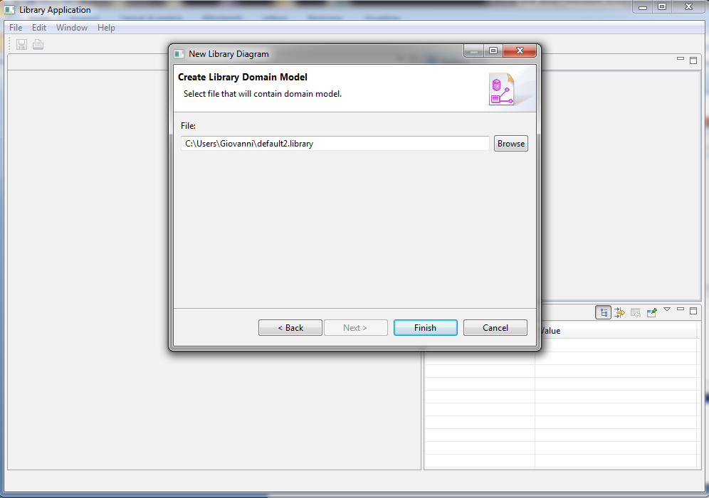
Let’s look at work: from the File menu choose New>> Diagram Library, starts a wizard that asks us to name the files that contain the diagram model and the domain model
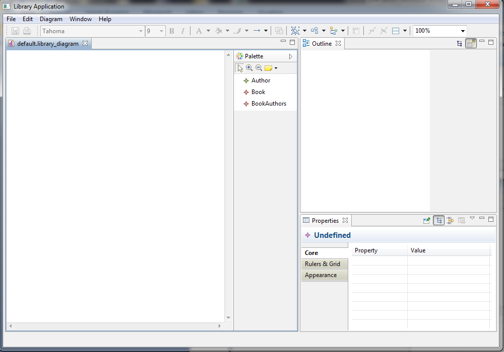
Clicking Finish will have the following result:
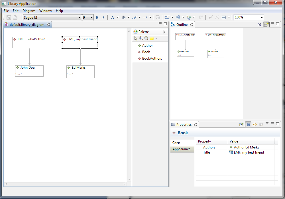
and, using the Palette, we can finally begin to populate our model.
Not bad for not having written a single line of code, donÔÇÖt you think? Sure, the graphic representation of the objects could be better, we have those pesky icons next to text labels, the names of the tools in the Palette are little explanatory… In the next installment we will explore some of the endless possibilities of “customization” offered to us by the GMF tooling, going to change these and other imperfections, and will explore the infinite capacity to regenerate the GMF code.


Ciao Vincenzo,
this diagram generates a new. library? and I would like to know where I can see the following tutorial on gmf
Ciao Silvio,
yes, a new .library is generated.
Regarding other tutorials on GMF we do not have them.
In fact, in the meantime, we started to use Eclipse Graphiti, which is far more easier to use.
We did not have written any tutorials on Graphiti until now, since the its Help system has already good tutorials.
Best regards
Vincenzo
Ciao Vincenzo,
ho seguito questo tutorial per creare la mia library application e l’ho portato a termine con successo.
Tuttavia ho riscontrato un problema con la vista ad albero nel pannello “Outline”: le etichette corrispondenti agli elementi del modello rimangono bianche, con l’unica eccezione degli elementi del modello che hanno un attributo denominato “name”.
Allego uno screen per maggior chiarezza:
screen_outline_tree
Come puoi vedere l’intero albero nella vista Outline è composto di etichette vuote, pur essendo queste selezionabili. Solamente gli elementi di classe Author (che hanno un attributo “name”) vengono mostrati.
Esiste un modo per rimediare al problema che non sia dotare tutte le entità di un apposito attributo “name”?
Ciao Fabio,
in EMF è possibile specificare quale tra gli attributi deve essere usato come Label Provider (di default viene usato l’attributo name appunto).
Per specificare tale attributo basta aprire il file .genmodel, selezionare l’entità e cambiare la proprietà Label Feature, selezionando da una lista uno degli attributi.
Poi si procede con le varie rigenerazioni di codice.
Ciao
Vincenzo
How do I Export the project into a executable file?
That’s not a straightforward path, but you can try creating a standalone application, like in
http://www.rcp-vision.com/come-creare-una-applicazione-eclipse-rcp
and then package previous plug-ins together with the application and have an overall standalone application with all of them.